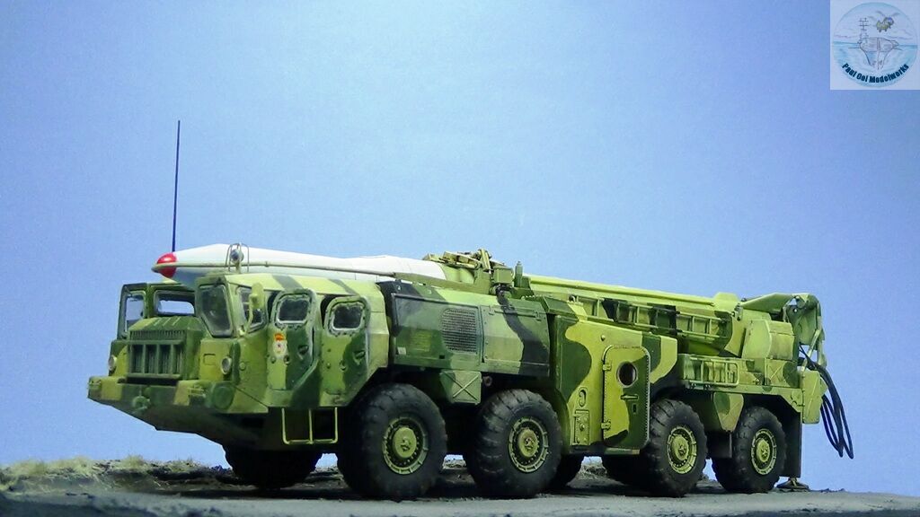
The Soviet tactical ballistic missile program started in the aftermath of WW2 when information obtained from captured German technology propelled that country into the missile age. In the 1960s and 70s, Western observers waited to see the types of Soviet missiles being displayed in the Red Square during the annual May Day celebrations. One of the most ubiquitous ballistic missiles spotted were the R-11 and the later R-17 models, often known by its NATO codename “Scud”. The Scud burst onto the world stage in the First Gulf War in 1991, when Iraq fired Scuds (B or C versions) into Israel and Saudi Arabia. In the Second Gulf War, Scud-hunting was a major priority of the US and her allies, evidence of the strong psychological effect of the weapon.
While the Scud B and C variants were inaccurate (an error of up to half kilometer radius), the more advanced Scud D developed in the 1980s was much more accurate with an error of only 50 meters radius. The missile warhead was fitted with a close guidance camera unit fitted on the nose. However by the late 1980’s, this variant of the Scud was overtaken by newer missile models like the SS21 and SS23. The Scud was popular among Soviet and Eastern Bloc client states because of its relative ease of operation, all neatly bundled into a compact package in a single launcher vehicle. This mobility and short launch preparation time (30-90 minutes) enabled Scuds to operate and then get out of harm’s way as was demonstrated by the Iraqis during the Second Gulf War.
Gallery
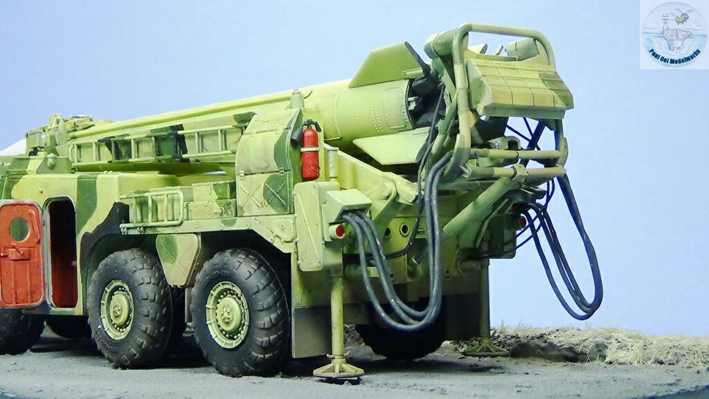
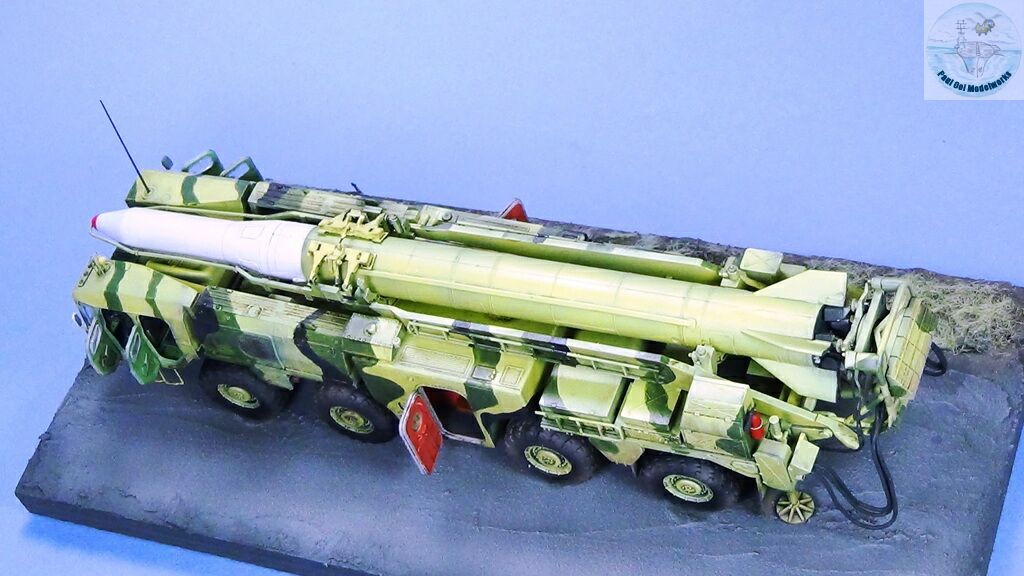
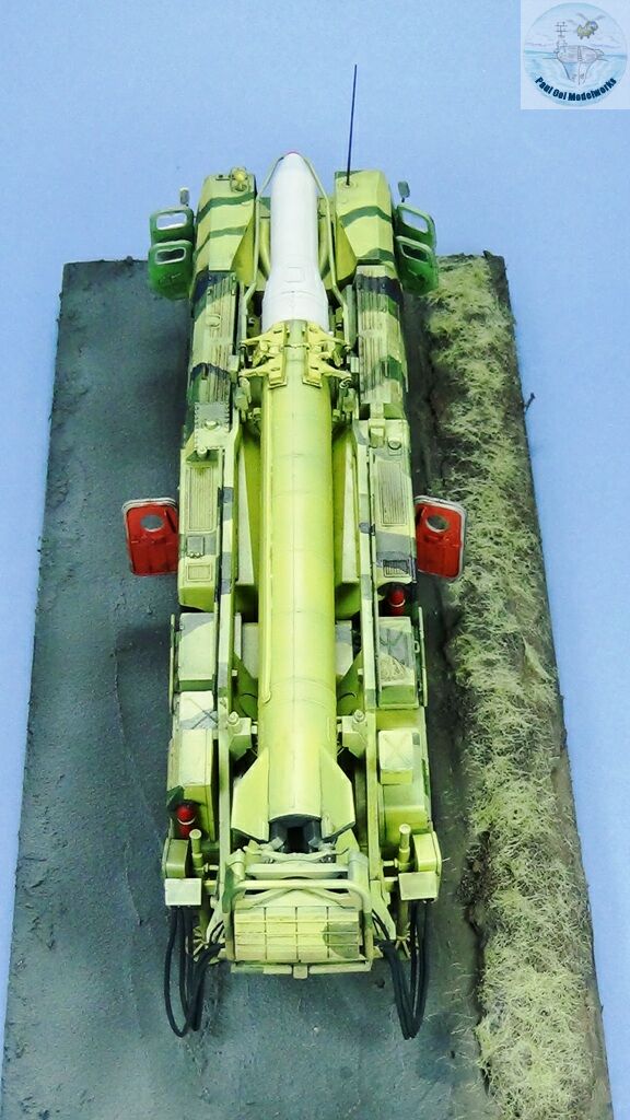
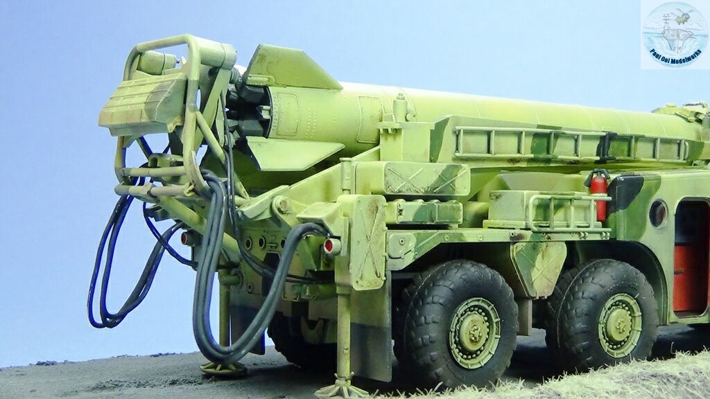
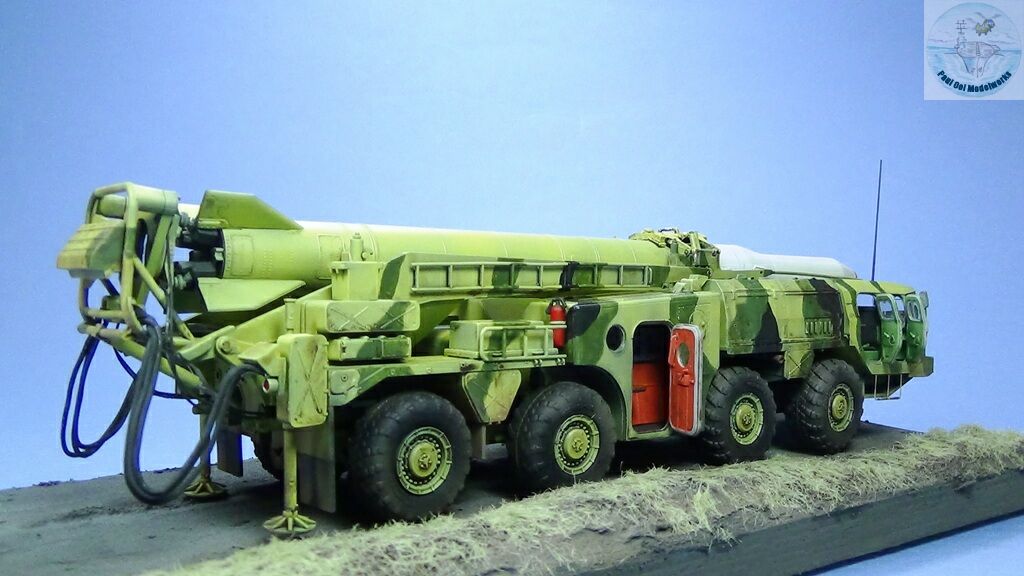
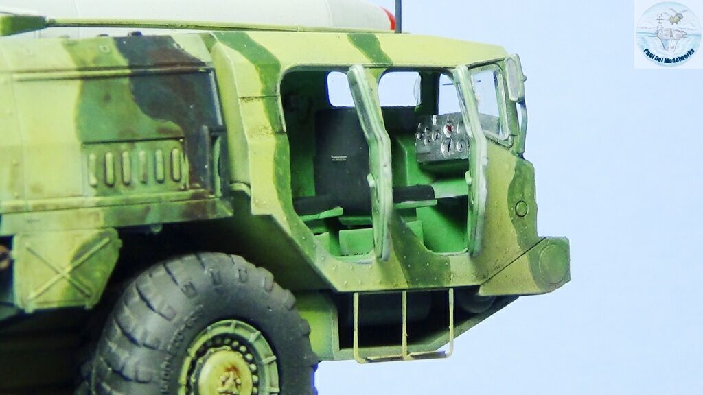
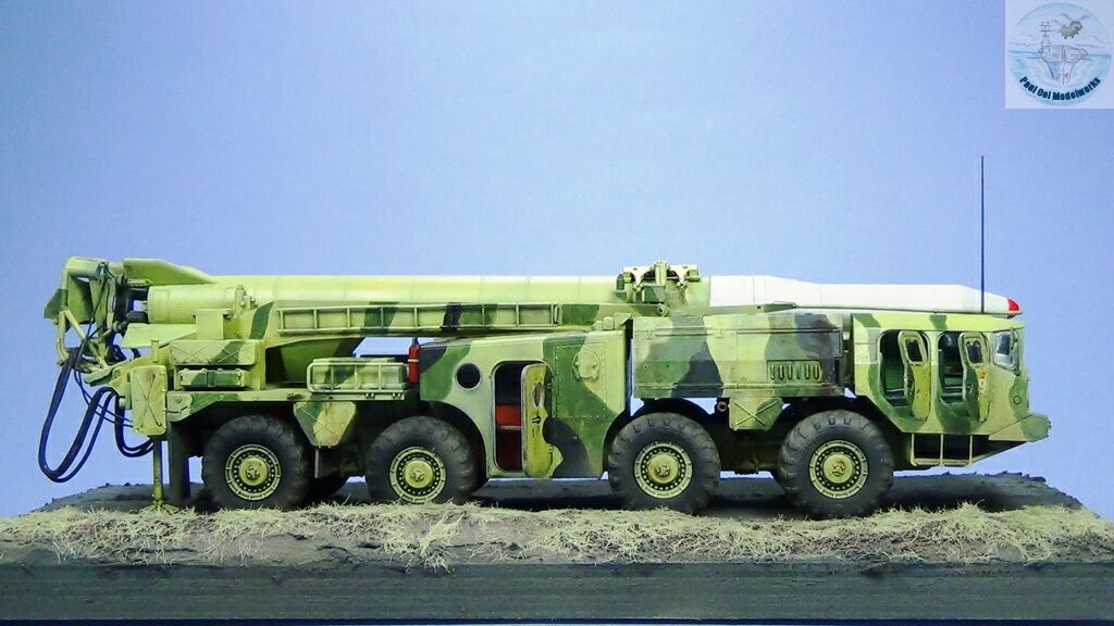
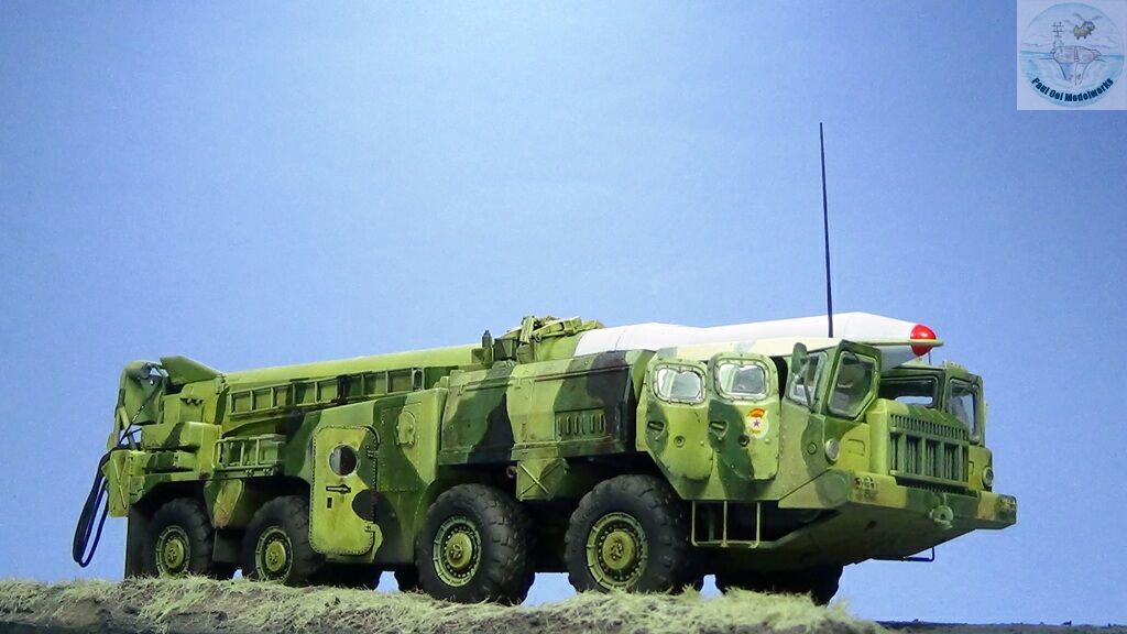
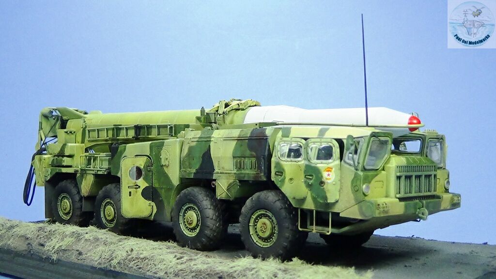
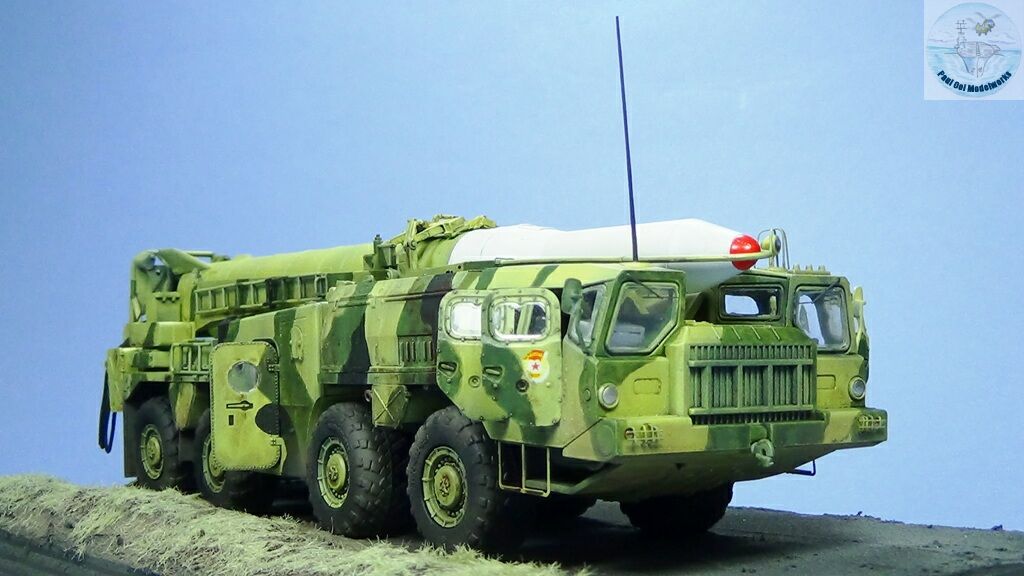
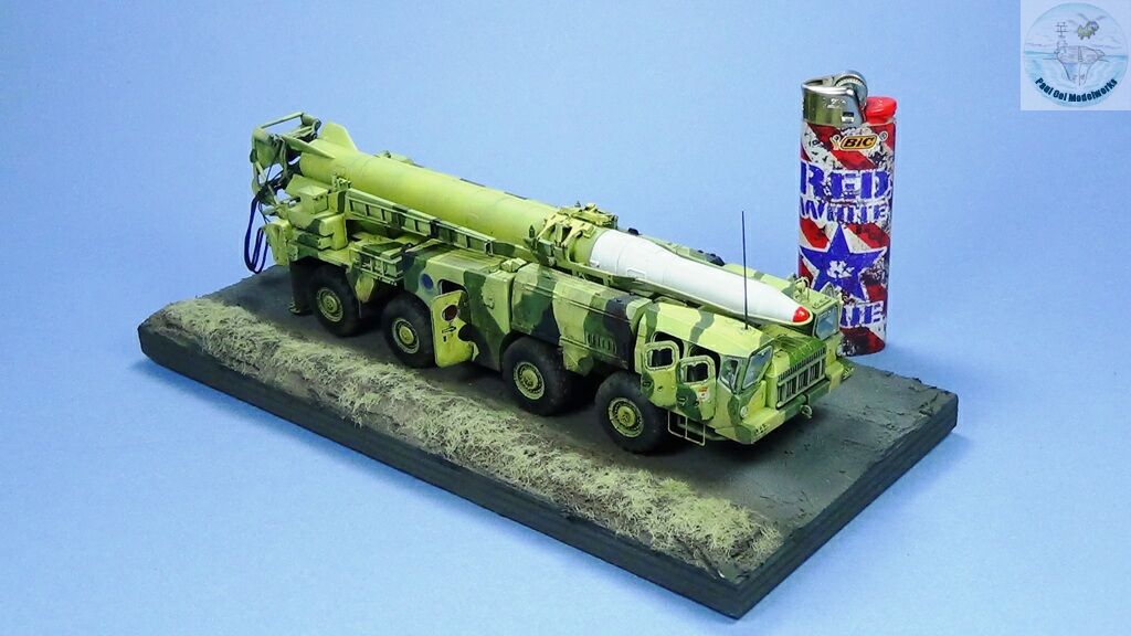
Construction Notes
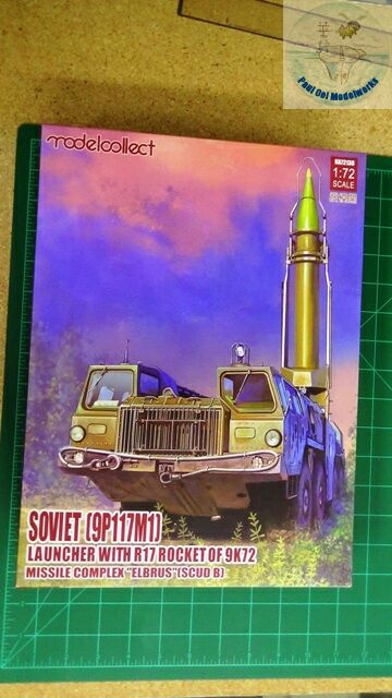
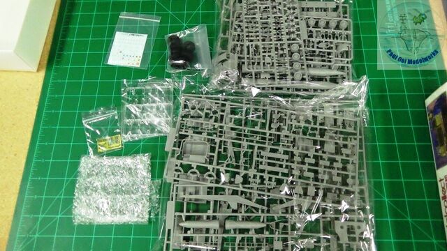
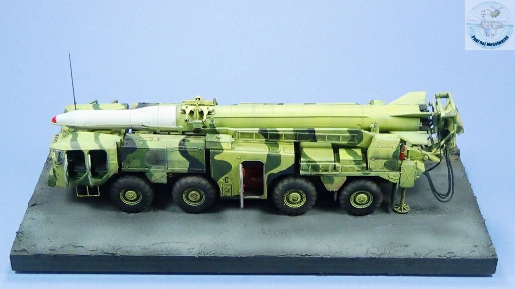
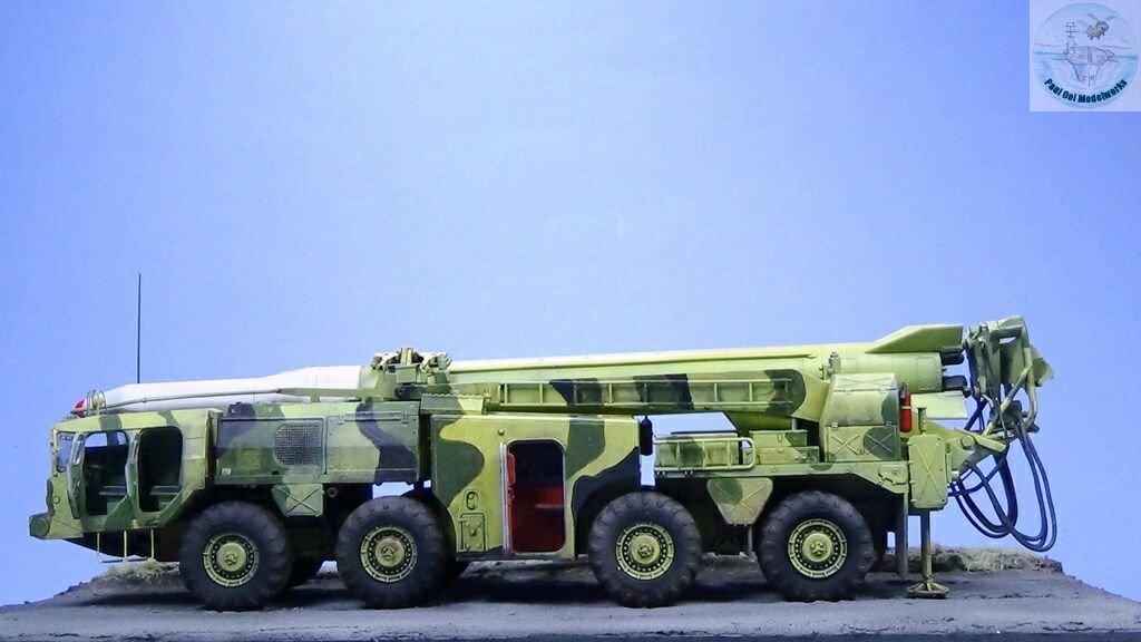
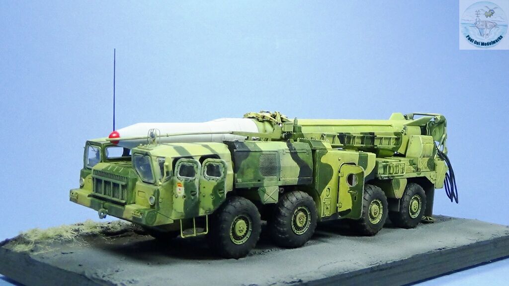
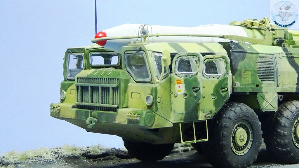
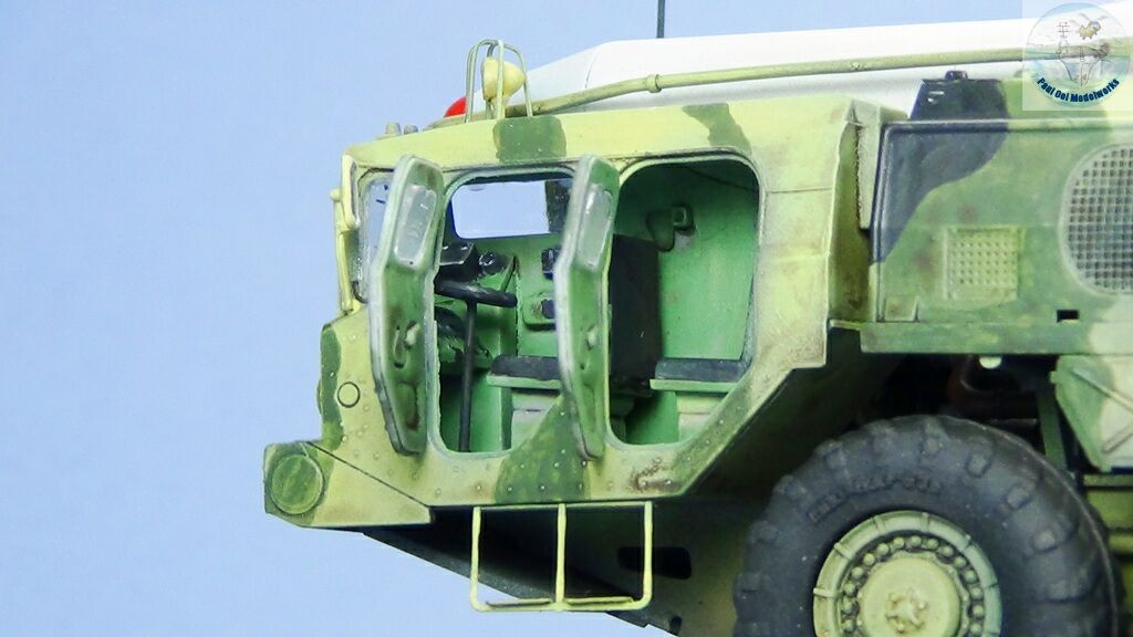
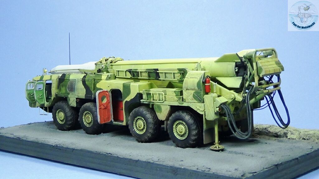
I have been intrigued by huge transporter trucks like the US HEMTT but when I saw this split cab arrangement for the Scuds, I was instantly sold. This 1/72 scale kit from Modelcollect China is labelled as Scud B but you could actually build all the main Scud variants from the early B through D. The parts are crisply molded and a small photoetch fret is provided for lamp guards and the step ladder to get into the front compartments. The instruction sheets do need some thinking through as they are not very specific about how some parts fit together. My two biggest complaints are that many parts that need through holes are in fact not and one has to drill through them to get the parts to fit, and that there are no instructions for the decals (although a nice decal sheet with lots of variants is provided). Other than that, this is one big challenging kit with tons of parts. It makes for a very rewarding build for the experienced modeler but I do not recommend this kit for beginners without guidance. For details and painting reference, I referred to the excellent walk-about gallery posted by Vladimir Yakubov in Silicon Valley Scale Modelers website.
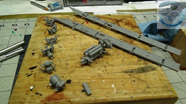 The chassis construction has many parts, most of them not visible once the truck is completed. However, they are necessary in order to provide the structural integrity of the parallel main beams. The engine and its huge twin fan radiator are very detailed but they cannot be seen once the front cab fits over them.
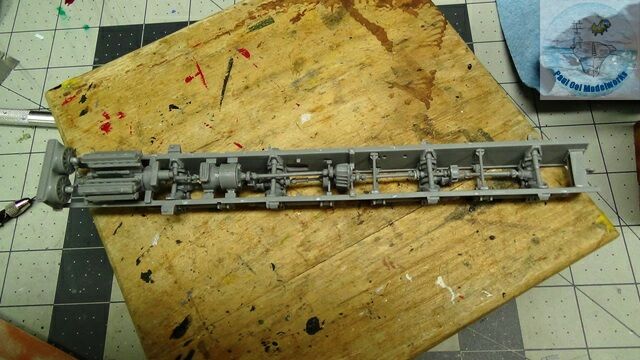 This is the main chassis assembly after the engine and transmission elements together with the connecting struts are in place. Do note that the right most connector box should not have been there as it later prevented the rear launch module from sitting in. It should have been taken out of the instructions.
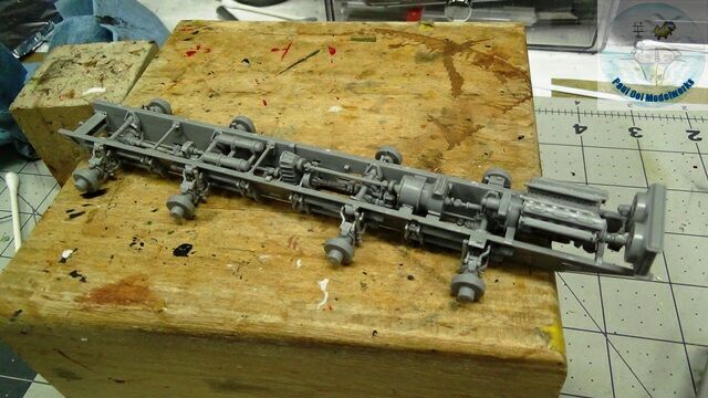 The wheel caliper sub-assemblies for all 8 wheels are now in place. Again, check with the elevation drawings in the instructions for the angle and attitude as these will determine the individual wheel alignments and the way it sits on a flat surface. Make sure they are all more or less level to each other or we will get lifted wheels.
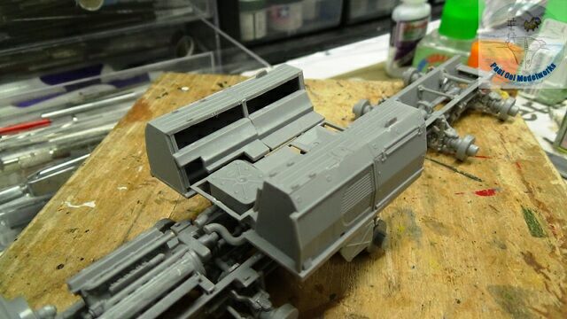 The power generator module is assembled and test fitted onto the main chassis. This is only a dry fit.
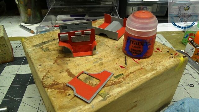
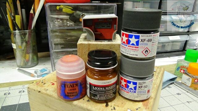
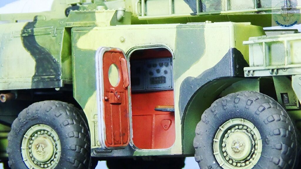
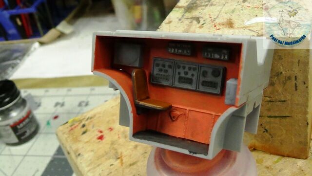 For the guidance control module, I start with the interior details as they are hard to reach once the walls come on. The best match for the red-brown interior color seen in Vladimir’s photographs is Citadel’s Squig Orange. The panels are Tamiya XF 53 Neutral Grey with black and white dials and Leather for the seats.
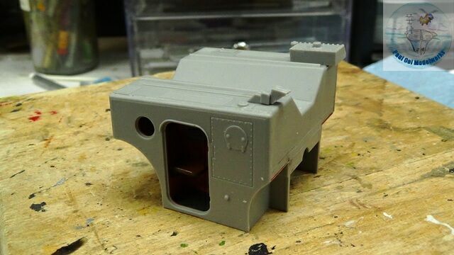
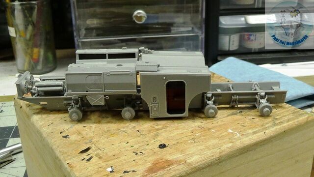 The guidance control module is enclosed and here you can see the trial fit onto the main chassis.
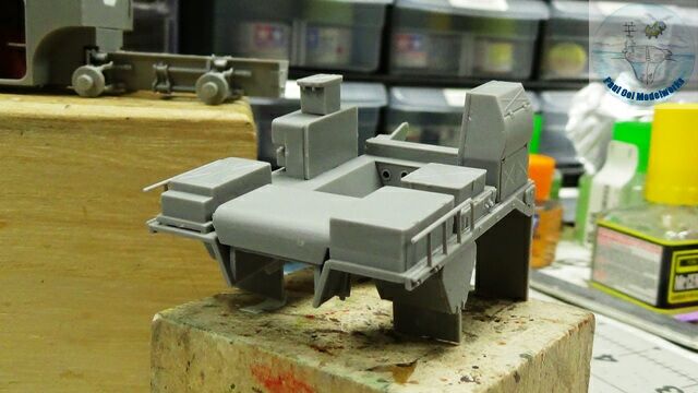 The main portion of the rear launch module is assembled for test fit onto the main chassis.
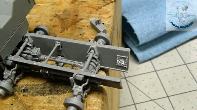
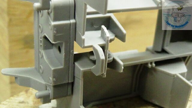
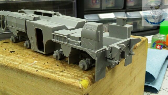 As mentioned earlier, there is an interference between the launch module and the last cross bar connector of the main chassis. The latter has to be removed in order for the launch module to sit properly onto the chassis. I saw off the hook plate and re-attach it to the underside of the launch module. The finished assembly is test fitted onto the main chassis.
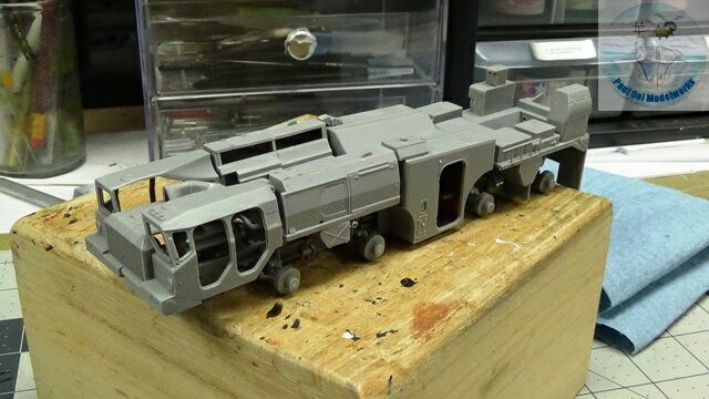 At this point, I put together all the major launch vehicle modules onto the main chassis for a dry fit trial to get the alignment.
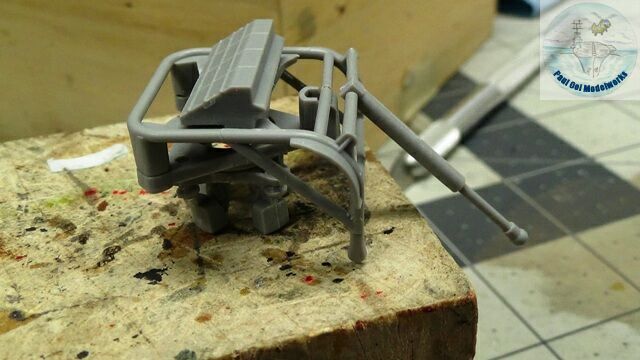 The rear launcher’s ignition frame now built. The alignment of the four rocket contacts are critical.
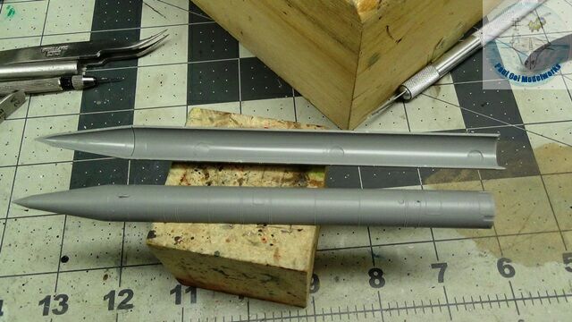
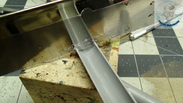 For the Scud missile itself, the kit has default parts for the Scud A-C warhead. In order to fit the VTO style Scud D warhead, the conical warhead has to be sawn off with a fine saw at the prescribed line.
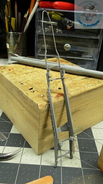 Once the missile is completed (see missile in the background), the launch cradle assembly is put together. It is necessary to have the missile in hand to check the fit and alignment of the cradle.
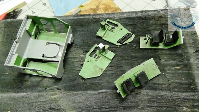
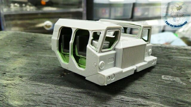 The front cab interior is painted in Model Master Pale Green (FS34227) as per Vladimir’s pictures. The cab outer housing is very tight and the sequence given in the instructions do not work well (build panels onto main chassis, slide outer cab housing over the main chassis). Instead the panels have to built into the cab as seen here in the second picture.
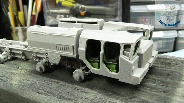 Because of the engine block and radiator assembly, the front cab has to be carefully eased onto the front of the main chassis. Once in place, the bottom splash plate is then glued onto the front cab to complete its assembly onto the main chassis. Here, I am test fitting the generator module to make sure that the spacing of the cab and module are correct.
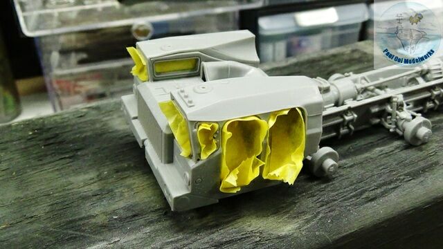
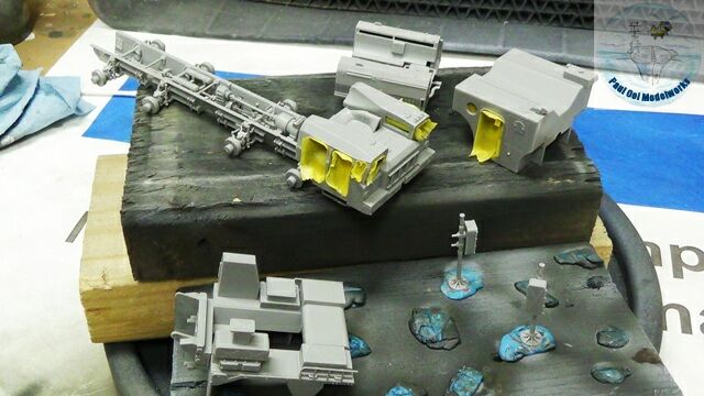 The front cab and guidance control module is masked in preparation for painting.
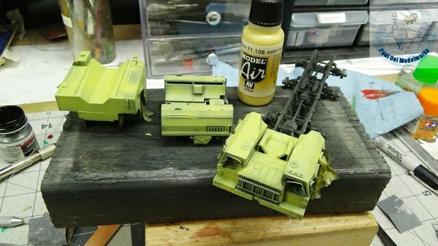 Using my typical under-shading method with black and grey, I finish the main color Valejo 71.106 Ivory which looks more like lime green.
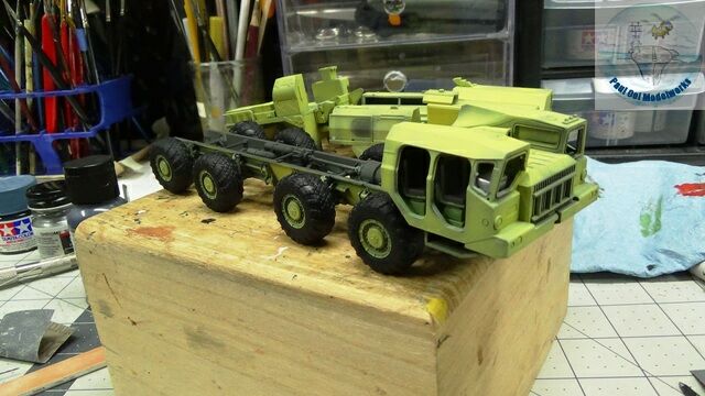
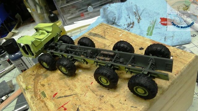 The poly tires are finally installed onto the main chassis.
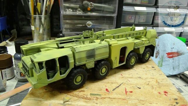 One more trial fit of the modules to make sure that the wheels clear the modules.
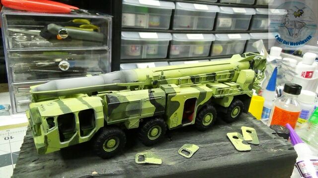 The camouflage patterns are hand-painted in Mission Models MMP-032 Modern Russian Green and Tamiya NATO Black XF69.
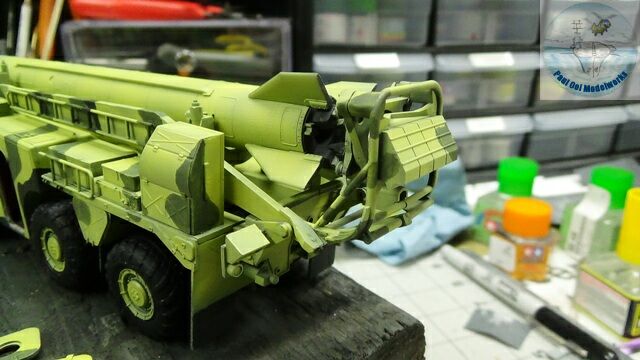 The ignition frame, and the missile cradle are installed onto the rear launch module. The missile itself is not glued to the ignition pads or cradle.
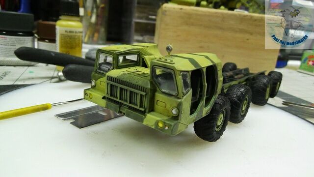 Glazing pieces are fitted onto the front cab. These require some care as some of the pieces do not fit exactly, and need to be trimmed down in size.
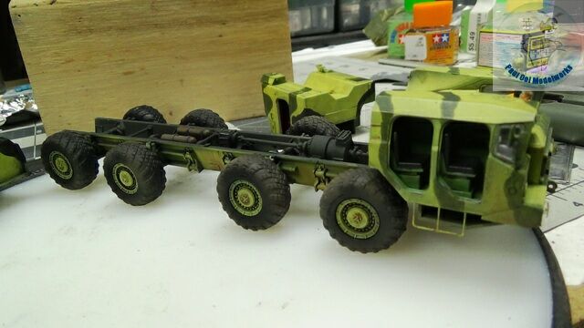 Removing all the modules (not glued yet), I apply an oil wash of 1:1 Burnt Umber: Lamp Black on the front cab and main chassis. Wash is also applied to the modules and missile.
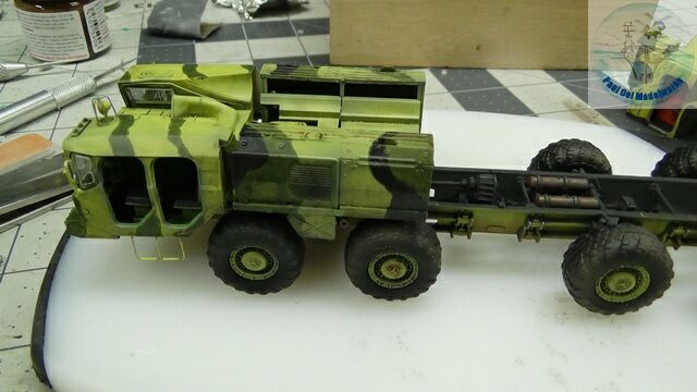
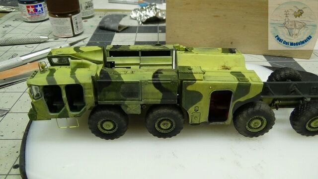
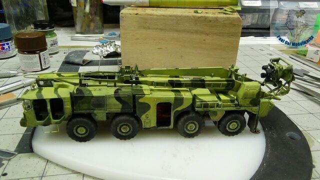 Now we can finally permanently install all the modules in sequence. The launch vehicle is all together now.
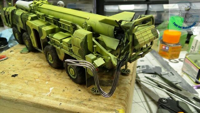
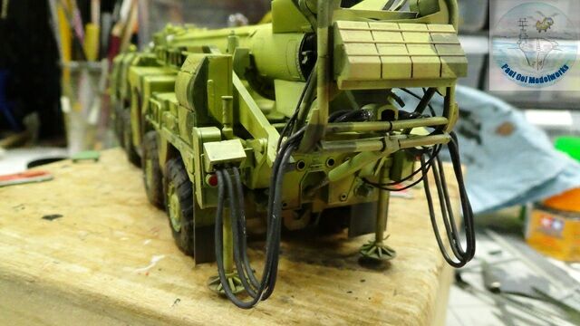 The connecting cables for the ignition frame are made from different sizes of solder wire.
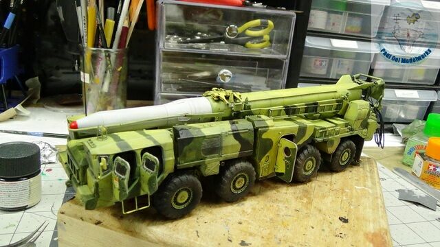 Final touches with the missile in place, the cradle clamps installed over the missile, and the doors fixed in the open position to reveal the interior.
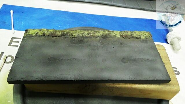 For the display base, I made a simple military road at the test site with a bit of dry grass edging it.


Bonjour
Votre montage m’est très utile
C’est une belle réussite 👍👍👍
Bonjour Francis, J’espère que votre projet sera également couronné de succès. C’est très amusant de construire ce kit. Paul